
In the previous article, we detailed the basic screw configuration for the feeding zone. In this chapter, we will introduce the screw configuration for the melting zone.
The melting mechanism in co-rotating twin-screw extruder is unique. Single screw process rely on heat from the barrel and friction between the barrel wall and the polymer conveyed between the screw flights to melt the polymer. In contrast, twin-screw extruders use kneading blocks to mechanically work the polymer, stretching, shearing, and folding it to generate heat. In this article, we will discuss how kneading blocks melt polymers and how the design of the melting zone affects the way the material melts, as well as the melt temperature and quality.
1.Function of the Melting zone
All compounding operations are performed in the molten state, but setting up the screw configuration to melt the polymer is not straightforward. An overly intense melting zone can lead to excessive melt temperatures, potentially causing polymer degradation or scorching if the polymer’s degradation temperature is exceeded. Conversely, too gentle a melting zone may fail to fully melt the polymer, resulting in an inhomogeneous product.
2. kneading element
Kneading element is composed of a series of discs or paddles, where each disc is offset from the previous one by a fixed angle. This stagger angle and the width of each disc determine the intensity of the work imparted by the kneading element. The direction of the stagger also determines whether the kneading element conveys material downstream (forward conveying) or upstream (backward conveying). Kneading elements are used not only for melting but also for mixing; mixing and melting actions occur simultaneously in the melting zone of the extruder.
a. Stagger Angle
Figure 2 shows a forward conveying kneading element. Looking at the end of the kneading element, each disc on this element is offset by 60° from its predecessor. Additionally, the general progression from one disc to the next is clockwise. This matches the rotation direction of the conveying screw. When this kneading element rotates within the screw, its rotation pushes the polymer forward—hence a forward conveying kneading element.
The stagger angle influences the energy transferred to the polymer, partly depending on the amount of material it conveys forward. For conveying elements, screw rotation pushes the polymer forward. Similarly, the forward conveying kneading element also pushes most of the polymer forward. Some polymers pass over the ends of the discs and is sheared at the barrel wall, some transfers to the adjacent kneading element on the other screw, and a small amount flows back upstream of the barrel. The combination of these three actions causes the polymer temperature to rise and conveys the polymer forward.
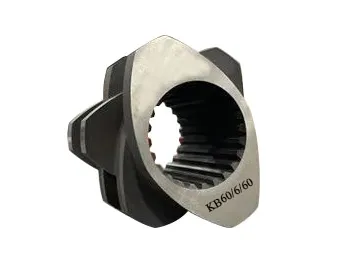
A method used by some manufacturers to label kneading elements can be seen in the etching on the side of the kneading element in Figure 2. The shorthand code for kneading elements uses the following format:
KB XX/YY/ZZ, where:
- KB — Stands for Kneading Block
- XX — The first number is the stagger angle. In Figure 2, the angle is 60°. In Figure 3, the angle is 90°.
- YY — The second number indicates how many discs the kneading block has. In Figure 2, there are 6 discs.
- ZZ — The third number is the length of the element in millimeters (in millimeters). In Figure 2, the shown kneading element is 60 mm long.
The kneading element with a 30° stagger angle provides minimal mixing and conveys material forward optimally. The 45° kneading element imparts more energy to the polymer while increasing mixing but conveys forward less efficiently. The 60° kneading element has poorer forward conveying capability but higher mixing efficiency and transfers more energy to the material.
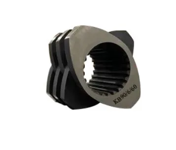
As the stagger angle increases, the forward pumping capability of the kneading element gradually decreases until the stagger angle reaches 90°. At 90°, the kneading element is in neutral position, and the polymer is mixed. Figure 3 shows a neutral kneading block with a 90° stagger angle. With reduced conveying capability, more polymer passes over the ends of each disc, causing more energy to be transferred to the polymer and increasing mixing.
b. Disc Width
Another factor that significantly influences melting effectiveness in twin-screw extruder is the width of the discs. Kneading elements typically consist of as few as three and as many as seven discs, commonly with four or five discs per element. Generally, the number of discs is constant, but the length of the kneading element is adjusted by varying the disc width. Wider discs impart more energy to the polymer. When the kneading element rotates in the extruder, the polymer can only flow in one of two directions: over the tips of each disc or around one disc to the next.
Increasing the disc width causes more polymer to flow over the disc tips. Narrow-disc kneading elements essentially slice through the polymer, while wide-disc acts more like a plough. The space between the disc tip and the barrel wall is where the shear rate is highest, the polymer passing through this zone experiences the highest shear forces in the extruder. The wide-disc kneading element imparts more energy to the polymer than the narrow-disc one, and this increased energy input leads to higher melt temperatures.
3.Reverse Conveying Kneading Element
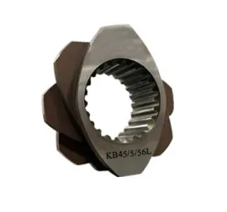
The final type of kneading element used in the melting zone is the reverse conveying kneading element. This type is the most severe as it pumps molten polymer back upstream. In this case, the smaller stagger angle results in the more intense action on the polymer.
Figure 4 shows the reverse conveying kneading element. For most manufacturers, forward conveying elements rotate to the right. The progression from one disc to the next in a kneading element is clockwise. Therefore, the reverse conveying element has paddles or discs that progress counterclockwise. These manufacturers use the same nomenclature as for forward conveying elements to specify reverse conveying elements, followed by “L”. “L” stands for left-handed, as these are left-handed elements, while forward conveying elements are right-handed.
4. Melting zone Screw Configuration
The design of the melting zone depends on the type of material being processed. When setting up the screw configuration for the melting zone, factors such as whether the polymer is crystalline or amorphous, whether the melt viscosity is high or low, or whether processing occurs near its decomposition temperature must be considered.
The condition of the compound is also crucial. Is only one polymer or a blend of several polymers fed through the feed port? What types of fillers and additives are added with the polymer? Does one or more additives have a melting temperature significantly lower than the polymer? Is a melting zone composed of consecutive kneading block zones appropriate, or is a configuration alternating kneading blocks and conveying elements a better design for the material being compounded… These factors all influence the screw configuration design.
The principles behind screw element function are a science, but screw configuration design is an art. In actual production, engineers may design different screw configurations to achieve the same function. This means there isn’t necessarily one design that is wrong and another that is right; they may just be different. However, if the product quality meets requirements, both may be acceptable.
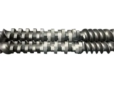
Figure 1 shows the melting zone of a 50 mm twin-screw extruder. Solid material is fed from the right side of the photo by conveying elements. The first element in the melting zone is a 30° kneading element, followed by three 60° kneading elements, with the final three 90° neutral kneading elements completing the melting zone.
As material enters the melting zone, it transfers from the conveying element to the 30° kneading element. This helps pull material into the melting zone and transitions from conveying to kneading while minimizing polymer backflow. The 60° kneading element then provides stronger work input to initiate the melting process while still conveying material forward.
The 90° kneading element serves two functions. The first is to apply higher energy to the polymer to melt it and raise the melt temperature to the desired processing temperature. The second function is to act as a restrictor, preventing material from passing through the melting zone too quickly. This ensures the local residence time of the polymer in the melting zone is sufficient to guarantee that all polymer passing through is molten. The restriction created by the 90° kneading elements acts like a melt dam, increasing the degree of fill of molten polymer in that region of the screw.
Some alternative designs include the following:
- Reverse Kneading Elements: Left-handed kneading element can be used to increase the amount of restriction at the end of the melting zone. Pumping material upstream by adding reverse kneading elements increases polymer residence time, improving melting, especially for crystalline polymers and high-temperature polymers.
- Reverse Conveying Elements: Left-handed conveying element is more severe than left-handed kneading element. This provides more backflow for better mixing, increased melt homogeneity, and higher melt temperature. Some formulations even require using a left-handed kneading element followed by the left-handed conveying element.
- Separating Kneading Elements with Conveying Elements: For some polymers, a single long series of kneading elements is not optimal and can lead to issues like excessively high melt temperatures or extruder surging due to uneven flow or incomplete melting. One approach is to design several short melting segments separated by conveying elements. This could be configured, for example, as two 45° kneading elements followed by a 90° kneading element, repeated once or twice, followed by a reverse 45° or 60° kneading element to ensure complete melting.
Now that the polymer is molten, we will discuss in the next article how to add other materials, such as liquids, low-melting-point additives, and fibers, to the melt.
The screw configuration in a twin-screw extruder’s melting zone critically determines melting efficiency and product quality. Nanjing Granuwel Machinery, as a professional extruder manufacturer with 20 years of expertise
For in-depth melting zone guidance or machine quotations,
contact us: www.granuwelextruder.com