
In the previous article, we discussed several fundamental principles of screw configuration and provided a brief overview of the basic screw arrangements in different sections of the extruder, including the feed section, melting section, mixing section, venting section, and homogenization section. In the next three chapters, we will focus on the screw configuration in the feed section of twin-screw extruders, the screw configuration in the melting section of twin-screw extruders, and the screw configuration for special materials in the side feeding section.
In twin-screw extruders, the screws are composed of a series of independent screw elements mounted on a core shaft. These individual screw elements can be freely combined along the length of the extruder and according to the different functional units of the barrel. Each screw element has a specific function, and even minor changes in the design and sequence of the elements can significantly affect the mixing, melting, or conveying behavior of the materials.
Now, we will introduce the screw configuration for the feed section of fully intermeshing co-rotating twin-screw extruders.
1. Function of the Feed Section
The function of the feed section is to receive the material entering through the extruder’s feed port and transport it to the melting section of the extruder. In general, single-screw extruders use a flood feeding method: the hopper is placed directly above the feed port of the single screw, and the material falls freely into the feed section of the screw due to gravity. The screw is filled with polymer or a mixture of polymer and additives. The rotation of the screw pulls the material into the extruder or molding machine.
Twin-screw extruders employ a starve feeding method: the feeder delivers material into the feed port at a stable and controlled rate. As a result, the processing rate of the twin-screw extruder is determined by the feeder and is independent of the screw speed. Since twin-screws are fully intermeshing, the screw volume is relatively small. If the feeder speed is too high while the screw speed is too low, material can accumulate in the feed section. Therefore, it is essential to control the amount of material entering the twin-screw to prevent screw jamming.
The part of the barrel where the material is fed is the feed port. This can be located in the first or second barrel section. The material can be free-flowing pellets, viscous mixtures (such as pastes), or lightweight powders. The screw in this section must be designed with a long pitch to ensure that the material falling into the screw is effectively conveyed into the extruder. Once the material is conveyed into the extruder by the screw, it is transported along the length of the extruder to the melting section, where the polymer will melt. We will discuss the melting section in detail in the next article.
The length of the feed section can vary depending on the overall mixing requirements. When designing the screw, it is important to consider the entire mixing process occurring in the extruder: whether it involves simply pelletizing polymer from powder, incorporating mineral-filled compounds, or adding masterbatches with high proportions of pigments and additives. The barrel’s feed section is water-cooled to delay the melting of the polymer, as premature melting in this area can cause the polymer to adhere to the barrel’s feed port, blocking the material flow. This would hinder the effective conveying of the polymer and reduce the equipment’s output. Therefore, the screw elements at the feed port should be designed with a large pitch to address this issue.
2. Screw Configuration in the Feed Section
a. Conveying Elements
The two primary parameters defining conveying elements are the length of the element and the axial distance (pitch) required for the thread to complete one full rotation around the element.
The longer the thread length (pitch), the wider the channel for conveying solids. Similarly, as the thread length increases, the material moves farther with each rotation. Conveying elements with short threads, also referred to as “tight-pitch” elements, transport material over a shorter distance, while elements with larger pitches convey material farther along the length of the extruder.
Most manufacturers use a pair of numbers to identify their conveying elements: the thread length divided by the length of the element. Examples of such labeling include:
44/44: A conveying element with a length of 44 mm, featuring a thread that completes one full rotation around the element while advancing 44 mm axially. See Figure 1.
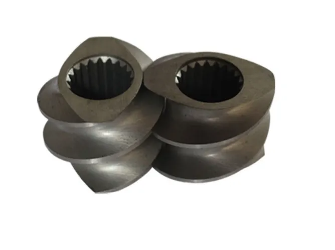
Figure 1: 44/44 Conveying Element
56/56: This element is similar to the 44/44, but the element itself is longer (56 mm) and requires 56 mm to complete one full rotation. The thread of the 56/56 element is much wider than that of the 44/44, allowing it to convey material over a greater distance. See Figure 2.
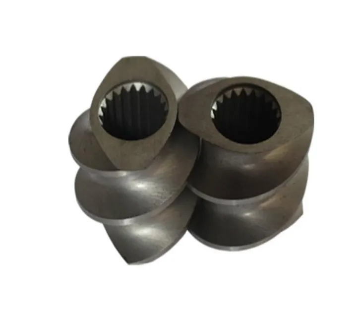
Figure 2: 56/56 Conveying Element
56/28: In this case, 56 mm is required to complete one full rotation, but the element itself is only 28 mm long. This type of element allows engineers to maintain a conveying distance of 56 mm while utilizing only 28 mm of space on the shaft. See Figure 3.
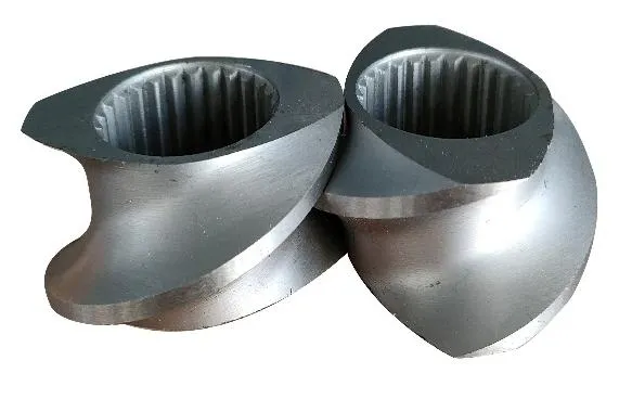
Figure 3: 56/28 Conveying Element
b. Feed Elements
Figure 4 illustrates a special element commonly used at the feed port of extruders, known as the SK element or feed element. Compared to standard conveying elements with curved surfaces, the blade on one side of the SK element that pushes the material has been cut off, creating a flatter surface. This design allows for greater axial pushing of the feed material.
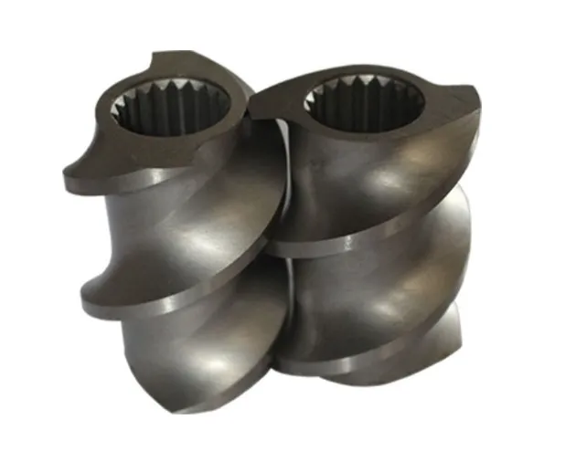
Figure 4: 72/72 SK Element
When designing the screw for the feed section, the goal is to collect the material falling into the feed port and convey it forward quickly. As shown in Figure 4, the SK element (feed element) is positioned directly below the feed port. Most manufacturers primarily use elements with a length equal to one full rotation, while others may produce longer elements. Following the feed element, standard conveying elements are typically used, often with the same thread length as the feed element, to ensure smooth and continuous forward conveying of the material.
c. Stub Shaft Element
Additionally, a tightly fitted stub shaft element (with a half-keyway) is placed at the first position on the shaft, upstream of the feed element. This acts as a mechanical barrier to prevent powder and small particles from leaking through the tail end of the screw.
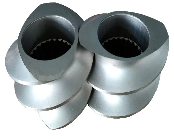
Figure 5: Stub Shaft Element
3. Screw Configuration for Powder Feed Section
Powder presents unique challenges for feeding, especially powders with low bulk density and very fine particle sizes. When lightweight powder falls through the feed hopper, air is carried down with it. The mixture of powder and air occupies a large volume, effectively clogging the feed port, which can reduce or even prevent polymer feeding.
Additionally, the entrained air must eventually escape from the extruder. The only path for the air to exit the extruder is upward through the feed hopper. Suspended powder accumulates until it falls into the feed port, repeating the process. Between feed port clogging and powder feeding interruptions, the entrained air can cause issues such as low feed rates and fluctuations.
Minimizing air entrainment and removing air from the powder are crucial for maintaining a stable feed rate. In our previous article (“Core Components Determining the Performance of Twin-Screw Extruders (Part 2): Barrel”), we discussed configuring the barrel so that the feed port is located in the second barrel section, while the air vent is positioned in the first barrel section. This allows the air entrained with the powder to escape through the rear vent of the first barrel section without interfering with the falling powder. This configuration makes powder feeding easier and can improve the feed rate.
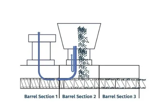
Figure 6
Figure 6 shows the feeding of powder in the second barrel section, with the first barrel section serving as the rear vent. The airflow is indicated by the blue arrows. Similar to the standard feed port configuration, the SK conveying element is positioned directly below the feed port, followed by standard conveying elements. Both the SK feed element and the conveying elements in this section should have the maximum thread length available for the given extruder, providing the widest channel to carry the powder.
Upstream of the feed port, conveying elements with a smaller pitch are used to continuously push the powder forward, again acting as a mechanical seal. The tighter the thread clearance, the more forward motion is available to prevent powder backflow. However, air can easily pass through and escape from the rear vent.
In the field of twin-screw extruder design and manufacturing, Nanjing Granuwel Machinery has always been at the forefront of the industry. We are committed to providing customers with efficient and reliable extrusion solutions, ensuring that every piece of equipment meets the processing needs of different materials. Whether it is the screw configuration design for the feed section, melting section, or other critical zones, Nanjing Granuwel Machinery leverages years of experience and technical expertise to offer customers the most optimized solutions. Our professional team not only focuses on the performance of the equipment but also pays close attention to detail, ensuring that every extruder operates efficiently while maintaining a long service life. By choosing Nanjing Granuwel Machinery, you gain not just equipment, but a trustworthy partner.
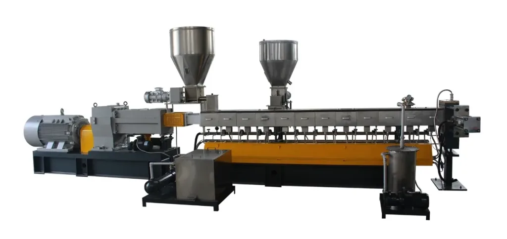
Granuwel Twin-screw Extruder