
在双螺杆挤出机中,螺杆主要分为进料段、熔融段、混合段、排气段和均化段。螺杆元件的主要功能包括输送、熔融、剪切、物料混合以及停留时间控制。双螺杆挤出机的螺杆元件采用”积木式”方式组合,可根据实际生产需求进行调整。因此,螺杆组合是双螺杆挤出工艺定制的关键所在。
同向双螺杆挤出机主要用于复合材料的混炼。螺杆组合需考虑主辅料的性质与形态、加料顺序及位置、排气口位置、机筒温度设置等因素。同时,由于混合对象极为复杂,每个具体的混炼工艺都需要设计合理的螺杆组合。尽管如此,同向双螺杆挤出机的螺杆组合仍有基本规律可循。
以下是螺丝组合的一些基本原则.
1. 进料口应采用大导程螺杆元件,以确保顺畅进料.
此处提到的喂料段不仅指第一主喂料口下方的螺杆段,还包括下游喂料口的螺杆段。喂料段的主要要求是能够平稳且自适应地添加各种物料,包括各种形状的颗粒、低堆积密度的粉末、纤维状添加剂等。该部分通常采用大导程、直角推力角、正向螺纹(通常为SK输送型)的输送元件。
在保持螺纹槽深度不变的情况下,较大的导程意味着更大的螺纹槽容积。对于第一个主进料口下方的进料段,它可以容纳并添加大量物料。对于下游进料口的进料段,由于物料从上游输送而来,可以形成较低的填充水平,以容纳新添加的物料。
大多数双螺杆挤出机采用标准的大导程等深螺纹元件。部分设备也会采用非标准的加深螺槽元件,以获得更大的喂料和输送能力。但采用加深螺槽的非标元件,必然会牺牲螺杆底径与芯轴花键之间的厚度,导致壁厚变薄。这可能会在生产过程中带来喂料段部件开裂、螺杆元件使用寿命缩短等风险。因此,在大多数情况下通常不会采用加深螺槽的设计。
2. 在熔融段,应首先使用小导程螺杆元件建立压力,从而压缩并熔融物料.
可设置90°错列角的捏合块来平衡压力,或使用30°错列角的捏合块对物料进行初步分布混合。捏合块应从熔融段中部开始排列,并注意均匀间隔。
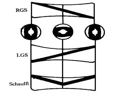
材料熔融的热源有两个:一是料筒加热器提供的外部热量,二是螺杆引入的剪切热,后者为主要热源。为引入剪切热,应在熔融塑化段设置捏合块、反螺纹元件和非标准转子型挤出机螺杆元件(图1)。这些元件需与上游正向螺杆元件在螺杆预定轴向位置有效组合,如图2所示。
RGS – 右旋螺纹元件
LGS- 左旋螺纹元件
Schauffl- 交替旋向螺纹元件
图1 转子式大导程螺纹元件
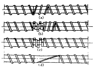
(a) 反向螺纹元件 (b) 正向捏合块 + 反向螺纹元件
(c) 正向捏合块 (d) 反向非对称大导程螺纹元件
图2 用于熔融的局部螺杆组合
评估熔融塑化段螺杆组合质量的标准,应以其将机械剪切能转化为热能的能力为依据,即在不过度提高物料温度的前提下,尽可能快速且彻底地熔融物料,也就是最合理地利用能量。
实验发现,图2中的配置b在螺杆高速运转时,物料迅速熔化且熔融区非常短。然而,在该段及上游区域,物料的温升非常高,远超原设定温度及物料熔化所需能量,熔体压力也极大。这表明该螺杆组合耗散过多机械能,不仅使物料熔融,还大幅提高了熔体温度,显然并非最优方案。
图2中的组合c展示了一种更优的熔融螺杆组合方案。该设计能使大部分材料处于可控且稳定的剪切力与压力作用下,从而有效保持材料低温状态。
为避免在熔融和塑化段产生过大的温度梯度,可以交替布置剪切元件和前向螺纹输送元件,将总能量输入按一定顺序分布在特定的轴向长度上,如图3(c)所示。
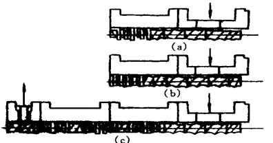
(a) 正向捏合块 + 反向螺纹元件 (b) 反向捏合块
(c) 正向捏合块与正向螺纹元件交替排列至排气口
图3 Granuwel 公司采用的熔融段螺杆组合
3. 混合部分的主要目的是剪切、精炼和分散材料颗粒。.
该段螺杆元件的配置极为复杂,要求设计者具备丰富的实践经验。此部分主要采用45°和60°交错角度的捏合块以增强剪切效果,并辅以齿轮状或“S”形等特殊元件。
然而,需要注意的是,捏合和剪切元件不应过度使用或排列过于紧密,以避免过度剪切。此外,为了增强该段的物料输送能力,还应穿插输送元件,即捏合块与输送元件应错开排列。
图4 展示了双螺杆组合设计中的一种螺杆配置,由齿轮状元件和其他增强分布混合强度的元件组成。图5显示了一种适合提高熔体混合强度的组合,由双头和三头捏合块构成。图6是一种用于分布和分散混合的螺杆组合,由捏合块和螺杆元件组成。
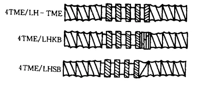
ME – 涡轮混合元件; LH 左旋;
KB – 捏合块; SB – 单头反向螺纹元件.
图4:W&P 公司采用的增强分布混合螺杆组合
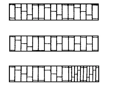
图5:由双螺纹和三螺纹捏合块组成的混合强度增强的混合段
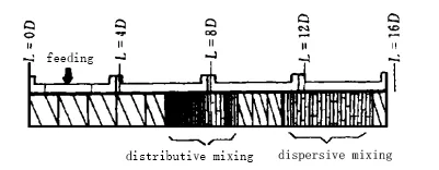
图6:由捏合块和螺杆元件组成的用于分布和分散混合的螺杆组合
图4 展示了双螺杆组合设计中的一种螺杆配置,由齿轮状元件和其他增强分布混合强度的元件组成。图5 显示了一种适合提高熔体混合强度的组合,由双头和三头捏合块构成。图6 是一种用于分布和分散混合的螺杆组合,由捏合块和螺杆元件组成。
4. 在排气口或真空口之前,应设置反向螺杆元件或反向捏合块.
在排气口或真空口处,应设置大导程螺杆元件。排气口或真空口之后,应设置小导程螺杆元件。这种组合可以尽可能去除材料中的挥发性成分。
同向旋转双螺杆挤出机设有排气区,用于去除物料中的水分、夹带空气和挥发性成分。在螺杆排气口上游应设置密封元件,以密封熔体并建立高压。排气区即螺杆面对排气口的区段,此处螺杆槽内的物料填充度应较低,并与大气或真空泵相连。
为了密封熔体并建立高压,可以使用反向螺杆元件或反向捏合块。在排气区,应采用大导程螺杆元件(图7),以形成低填充度和薄熔体层,使材料具有较大的暴露自由表面和较长的停留时间,从而有利于排气。
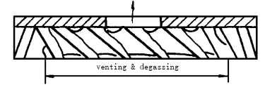
图7: 排气区的螺钉组合
5. 在均质段,应逐渐减小螺杆导程以增加压力并缩短背压段的长度.
同时,应使用单头螺纹元件和宽螺距螺纹元件来增强排料能力,避免物料溢出。
最后需注意的是,各功能段的螺纹组合必须根据具体的混炼任务(共混改性或填料改性)以及混炼工艺的要求进行选择。
南京格兰威机械通过多年的研究与实践,总结出了双螺杆挤出机的螺纹组合原则。这不仅为行业提供了宝贵的参考,也为企业自身带来了显著的技术进步和市场竞争力。我们相信,随着这些原则的广泛应用与不断优化,整个塑料加工行业将被推动向更高效、更环保的方向发展。